

Displays Control
Overview
The Displays Control widget lets you inspect and configure the display system of a computer running Screenberry Server. It is especially useful when you manage the computer remotely and its Windows desktop is difficult to navigate because of a large or unusual display layout.
Displays Control is available when Screenberry Panel is connected to Screenberry Server running on Windows. It contains two tabs with different hardware requirements:
- GPU Topology inspects NVIDIA GPUs and GPU ports and provides EDID, Mosaic, and frame-synchronization controls. It requires a supported NVIDIA GPU.
- Displays inspects and configures the logical displays exposed by Windows. It works with any GPU supported by Windows.
Changes made through Windows or NVIDIA utilities are reflected in Displays Control. Changes applied in Displays Control are reflected in Windows.
Note: Displays Control manages the Windows and GPU display configuration. The Display Editor performs a different task: it arranges Screenberry content on the output canvas.
Inspect GPU Topology
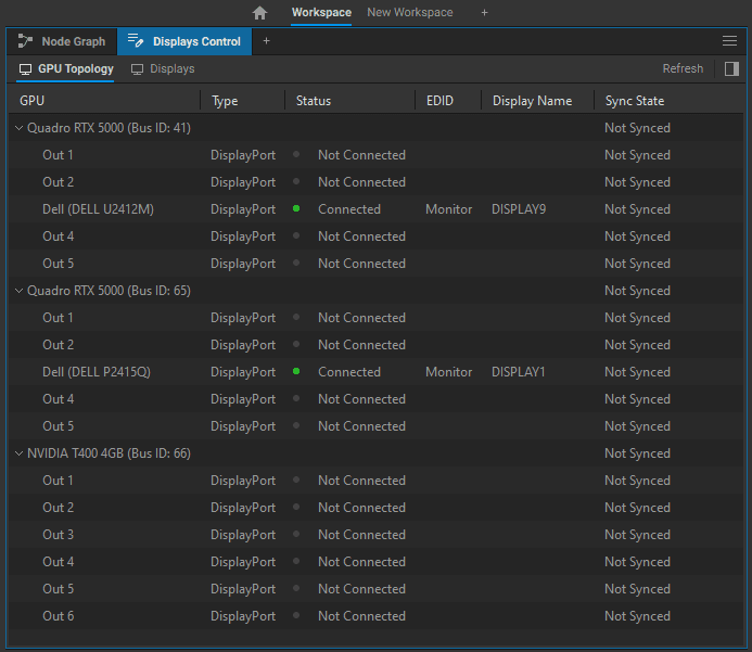
Open GPU Topology to inspect the NVIDIA GPUs installed in the server and the ports reported by the NVIDIA driver. Expand a GPU to see its ports, then select a GPU or port to open its information panel.
The topology includes the following information:
- GPU - the GPU, GPU port, or connected display.
- Type - the connection interface reported for the port, such as HDMI or DisplayPort.
- Status - the current connection and Windows desktop status.
- EDID - Monitor when the EDID comes from the connected display, or Forced when an EDID override is active.
- Display Name - the display name reported through EDID.
- Sync State - Not Synced, Sync Source, or Synced.
Understand port status
The Status column distinguishes between the physical connection and the way Windows is using the display:
- Not Connected - no display connection is detected.
- Connected - the display is connected and active.
- Connected, Not Active - the display is physically connected but is not active in the Windows desktop configuration.
- Connected, Cloned - the display is active as part of a cloned Windows display configuration.
Some physical connectors may appear as more than one logical GPU port. This can occur when the NVIDIA driver reports separate HDMI, DisplayPort, DVI, or adapter signal modes for the same physical connector. Use the topology as the driver’s logical view of the GPU rather than as an exact map of the card bracket.
Review GPU and port information
Select a GPU to review GPU Info, including GPU Name, Slot ID, Bus ID, PCI Device ID, PCIe Lanes, Bus Bandwidth, Serial Number, and VBIOS Version.
The PCIe Lanes and bus values can help diagnose a card installed in an unsuitable slot or operating with fewer PCIe lanes than expected.
Select an output to review its GPU Port information, including its connection interface, EDID state, synchronization status, and whether it is an Eligible Sync Source.
Manage EDIDs
EDID (Extended Display Identification Data) describes the video modes and capabilities that a display reports to the GPU. An EDID override is useful when a server must retain a predictable output mode while a display is disconnected, powered off, or replaced.

Note: EDID forcing is available only with NVIDIA Quadro-series GPUs. Use Reset EDID to remove a forced EDID and return to the monitor’s native EDID.
The available EDID actions are:
- Dump EDID - save the EDID currently reported on the selected port.
- Force EDID - load an EDID file and apply it to the selected port.
- Quick force EDID - create and apply an EDID from a timing preset or custom timing values.
- Reset EDID - remove the forced EDID and restore normal display detection.
Create and force an EDID
To create an EDID with Quick force EDID:
- Select the required timing standard.
- Select a video-mode preset.
- Review the generated timing parameters.
- If necessary, edit the pixel clock, active area, blanking intervals, front porch, sync width, interlacing, or sync polarity.
- Select Force EDID.

Important: Only enter custom timing parameters when you know the values required by the output system. The values are interdependent, and an invalid combination can produce a signal that the connected display cannot show.
When the EDID column shows Forced, the GPU treats that port as connected even if its cable or display is disconnected. Screenberry can continue producing the forced video mode, but it cannot reliably report whether a physical display is present. A display that does not support the forced mode may show no image.
Create a Quick Mosaic
NVIDIA can combine multiple physical outputs into one logical display. This feature is called Surround on NVIDIA GeForce GTX/RTX GPUs and Mosaic on NVIDIA Quadro GPUs. Windows and Screenberry then see the complete surface as a single display.
Use Quick Mosaic for a regular grid that does not require manual display positioning or advanced NVIDIA Mosaic options:
Important: On Quadro systems, force an EDID on every GPU port that will participate in the Mosaic before you create it. This helps keep the Mosaic configuration stable if a display is powered off or disconnected.
- Make sure every required display is connected and active.
- Open Quick Mosaic from GPU Topology.
- Select the Topology, expressed as columns x rows.
- Enter the Width and Height of one display.
- Enter the required Refresh rate.
- Select Create.
For example, two 1920 × 1080 displays in a 2 x 1 topology create a 3840 × 1080 logical display. A 1 x 2 topology creates a 1920 × 2160 logical display.
After the Mosaic is created:
- The affected port names in GPU Topology identify their Mosaic membership and position.
- The Displays tab shows the complete Mosaic surface as one Windows display.

Warning: Do not disconnect display cables while Mosaic is active. A connection change can break the Mosaic configuration and may destabilize applications using NVIDIA or OpenGL resources.
Use Remove Mosaic to return the Mosaic to individual Windows displays. Windows or the NVIDIA driver may rearrange the displays or leave a display inactive afterward. If this happens, open Displays, select the inactive display, and select Extend.
Use NVIDIA Control Panel instead of Quick Mosaic when you need manual display placement or advanced Mosaic settings.
Configure Frame Synchronization
Frame-synchronization controls require compatible professional NVIDIA GPUs and a separate NVIDIA Quadro Sync board. They are not available for consumer GeForce configurations.
When Screenberry detects a Quadro Sync board, it appears as an additional device in GPU Topology. Screenberry uses the following synchronization terminology:
- Timing Server provides the reference timing signal.
- Client follows the timing signal supplied by a Timing Server.
- Eligible Sync Source identifies a GPU port that can be used as a synchronization source.
- Not Synced means that the port is not synchronized.
- Sync Source means that the port is currently providing synchronization timing.
- Synced means that the port is following a synchronization source.
Use Set as Timing Server to configure the timing source and Follow Timing Server to configure a client. Quadro Sync connections can extend between media servers, allowing the outputs of a multi-server cluster to follow a common Timing Server.
Manage Windows Displays
Open Displays to inspect the logical displays currently exposed by Windows. This tab works with any GPU supported by Windows.
For each display, the list shows:
- Name - the display identifier assigned by Windows.
- Video Mode - the active resolution and refresh rate, shown in a format such as 1920 × 1080 @ 60.01 Hz.
- Desktop Mode - Extended or Cloned, depending on the active Windows configuration.
Change the video mode
To change a display’s video mode:
- Select the display.
- Select a Resolution.
- Select a Framerate.
- Enable or disable HDR when the display and GPU configuration support it.
- Select Apply.
The available resolutions and frame rates come from Windows and the active display configuration. If you change a value without selecting Apply, changing the selection or refreshing the configuration restores the active value.
Important: Select a mode supported by the display and your remote-administration setup. An unsupported mode can leave the display without an image or make the remote desktop difficult to operate.
Identify displays
Select Show Identifiers to show the Windows identifier on the physical displays. Select Hide Identifiers to remove the identifiers.
Identifiers are useful when several outputs use the same display model or when the Windows display order does not match the physical arrangement.
Activate a connected display
A display can remain physically connected while its Status is Connected, Not Active. To add it to the extended Windows desktop:
- Open Displays.
- Select the inactive display.
- Select Extend.
Change a cloned configuration to extended
When Desktop Mode is Cloned, the targets can use different underlying video modes. For this reason, Screenberry may not show a reliable Video Mode for the cloned configuration.
Select Extend to separate the cloned targets into individual Extended displays. Each display can then be configured independently.
Route Content to Physical Outputs
The Canvas defines a content layout. Each Display Output node renders the content connected to its own inputs on the selected physical GPU output.
To route content to physical outputs:
- Add the required Display Output nodes to the Node Graph.
- Keep the Canvas node required by the output configuration in the node graph.
- Connect the content required for each Display Output node: connect Display nodes to its Displays input, patch nodes to its Patches input, or an image source to its Background Image input, as appropriate for the composition.
- In each Display Output node, select the corresponding GPU output device.
- On NVIDIA or AMD systems, select Offscreen in the Canvas node settings so that the Canvas does not create its own output window.
Note: Each Display Output renders the content connected to its own inputs. Keeping a Canvas node in the graph and choosing an output device do not automatically copy the Canvas composition to that output.
Important: Do not enable Offscreen on systems that render through an Intel GPU. It can cause graphical artifacts or repeat only a few rendered frames.
As a workaround, set the Canvas Image Size to 1 × 1 px and disable window options such as Always on Top. The windows created by the Display Output nodes can then cover the Canvas window.
For best performance, connect the output displays to the discrete NVIDIA GPU and operate Screenberry Panel remotely from a separate computer. Avoid running Screenberry Panel and Screenberry Server as the primary control workflow on the same machine, because interacting with the Panel can take focus away from the server output application.
Last updated on