Calibration Process
Automatic Calibration Presets
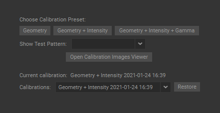
The Calibrator Wizard widget (Window > Calibrator Wizard) offers three calibration presets:
- Geometry calibration provides geometry alignment and edge blending. It normally takes about 30 seconds per projector and includes the Masks, Geometry, and Blends calibration stages.
- Geometry + Intensity calibration provides geometry alignment, edge blending, and black and white level compensation. It normally takes about 1.5 minutes per projector and includes the Masks, Geometry, Blends, and Intensity calibration stages.
- Geometry + Intensity + Gamma calibration has all the Standard calibration features with the addition of gamma correction to ensure image color uniformity within blends. It usually takes about 15-30 minutes and includes the Masks, Geometry, Blends, Colors, and Intensity calibration stages.
Note: The initial Geometry + Intensity and Geometry + Intensity + Gamma calibration may take longer as more pictures at a slow shutter speed should be taken for automatic adjustment of the camera for black calibration.
Note: Once the Gamma Correction calibration stage is completed, the gamma correction maps are stored in the LUT tables and applied every time that the Geometry and Geometry + Intensity calibrations are run.
Note: The Geometry + Intensity + Gamma preset is required only if you are using DLP single-chip projectors with Brilliant Color enabled. This calibration is required for the initial setup, or in any of the following cases:
- After the projector lamps have been replaced following extensive use.
- When visible color shifts in the blends between projections become apparent.
- After the projector color mode (Presentation (Game, PC), Cinema, sRGB, etc.) had been changed.
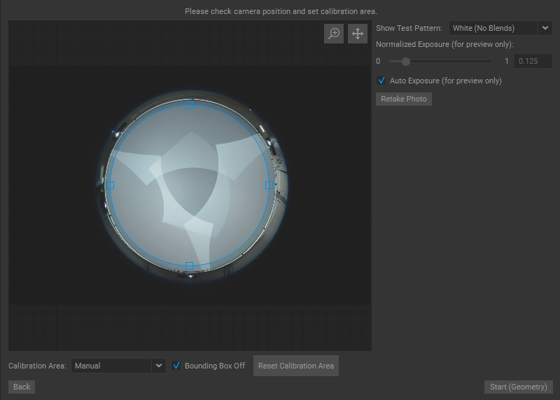
Checking Projectors and Camera Positioning
When the calibration preset is selected, the system automatically takes a test photo.
If the camera is not connected or not functioning properly, an Error message will appear.
Based on the test photo, adjustments can be made, if necessary, to:
- Camera rotation and tilt.
- The positioning of projectors to change how projected images overlap.
- The positioning and focus of the camera.
After adjustments are made, press the Retake Photo button ![]() to take another test photo. Make further adjustments if necessary. Repeat these steps until the camera and projection layout are set up as required.
to take another test photo. Make further adjustments if necessary. Repeat these steps until the camera and projection layout are set up as required.
Defining the Calibration Projection Area
The objects outside the projection area (light sources, trusses, etc) can reflect or emit light and, thus affect the calibration results — distorting calibration geometry or influencing black level compensation and brightness balance. Therefore, it is important to precisely define the projection area — anything inside the specified area is calibrated while everything outside is ignored.
Open the Calibration Area dropdown menu to select one of three screen area setting modes:
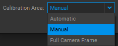
-
Automatic. Using the calibration patterns, the Calibration Wizard identifies the borders of the projection area automatically.
-
Manual (recommended). In this mode, a user can manually define a more precise bounding shape for the projection area. This approach significantly improves calibration quality by excluding undesired areas that should not be covered by the projection.
To adjust the mask, do the following:
-
In Bounding Box mode, scale the mask by dragging the handles.
-
In Circular mode, apply fine adjustments to the mask by dragging the handles on the curve. You can switch to this mode by selecting the Bounding Box Off checkbox
 .
.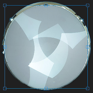
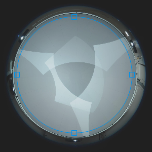
Bounding Box mode Circular mode
-
For more adjustment precision, zoom and pan the view by using the mouse scroll wheel (scrolling it to zoom, and holding it to pan) or by clicking the Zoom ![]() and Pan
and Pan ![]() buttons in the top right corner and moving the mouse.
buttons in the top right corner and moving the mouse.
To reset the mask to its default state, press the Reset Calibration Area button ![]() .
.
Note: The mask settings defined by the user are saved automatically, and loaded during the next calibration session.
- Full Camera Frame. In this mode, the Calibration Wizard automatically recognizes the entire photo frame as a projection area and positions the content to fit within the borders of the test photo.
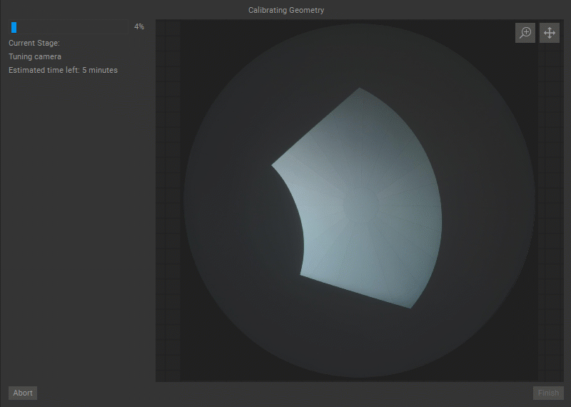
Running Calibration
Once the calibration projection area is defined, press the Start (Selected Calibration Preset) button ![]() to start the calibration. During calibration, the Calibrator Wizard displays the calibration progress bar, the current calibration stage, and photos of the calibration patterns projected on the screen.
to start the calibration. During calibration, the Calibrator Wizard displays the calibration progress bar, the current calibration stage, and photos of the calibration patterns projected on the screen.
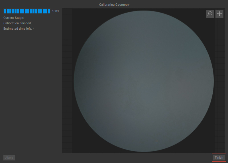
The calibration process can be interrupted by pressing the Abort button ![]() . The Abort button stays active during calibration and deactivates once the calibration process is finished successfully.
. The Abort button stays active during calibration and deactivates once the calibration process is finished successfully.
Press the Finish button ![]() when the calibration process is completed. The Finish button is inactive during the calibration process and activates when calibration is completed.
when the calibration process is completed. The Finish button is inactive during the calibration process and activates when calibration is completed.
Important: To achieve the best calibration results, during the calibration process:
- No object or person should obstruct the projectors’ light beams. If during the calibration the presence of personnel is required, they must remain below the projection line and out of camera view range.
- No light sources should be present in the dome. Lamps, monitors, phone screens, etc. should be turned off or, at the very least, set to minimum brightness.
Stages of Automatic Calibration
-
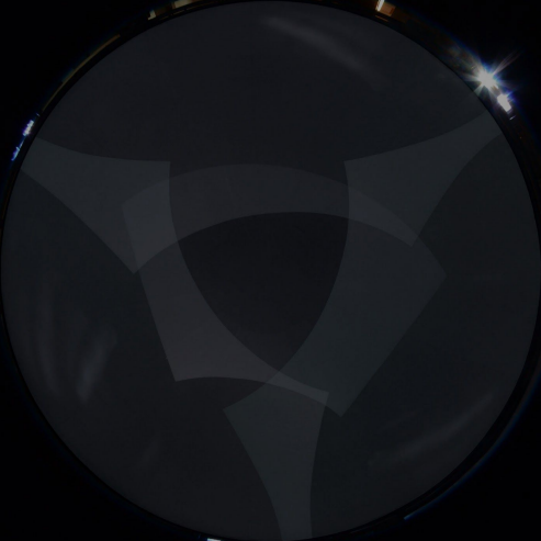
During the Masks stage, a series of black and white line patterns are generated to define a projection area for each projector.
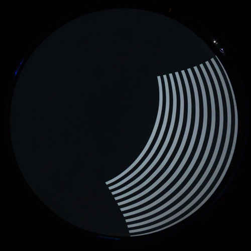

Black and white line pattern Resulting mask -
During the Geometry stage, a series of blob patterns is projected to generate the displacement maps for each projector.
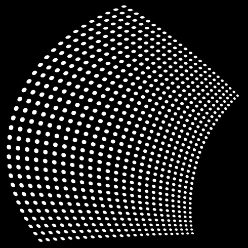
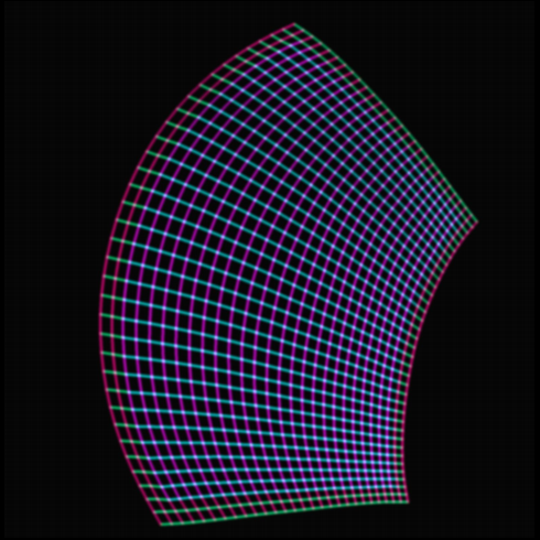
Geometry pattern blobs Generated geometry displacement map -
The Blends stage is used to generate brightness gradients for each projector to enable a smooth and even transition for the overlapping areas between projections.
Projector #1 blend map Projector #2 blend map -
The Gamma Correction stage is used to compensate for visible color/brightness shifts caused by non-linear gamma distortions that can occur when color modes with “boosted gamma” (like Brilliant Color) are set on DLP single-chip projectors. A series of color patterns are projected, and as a result, a Look Up Table (LUT) for a specific projector model is generated.
Example of color patterns used for Gamma Correction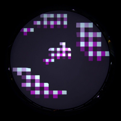
Note: The Gamma Correction calibration stage is required for the initial setup, after projector lamp replacements, or following extensive use, when visible color/brightness shifts in the blends between projections become apparent, which can be checked by using the Red, Green, Blue test patterns.
-
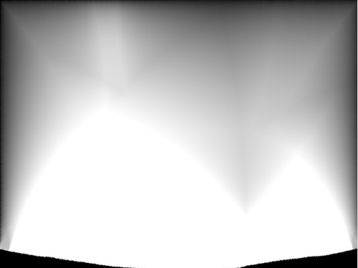
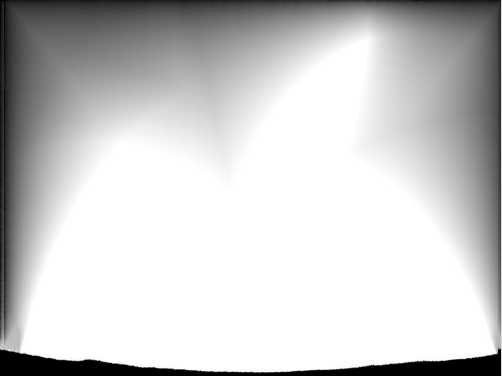
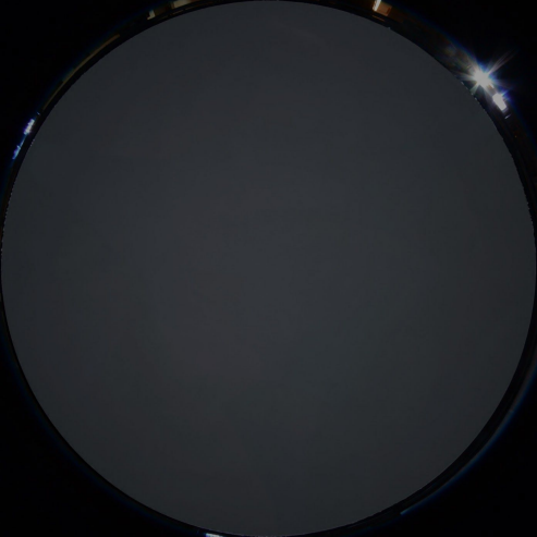
The Intensity stage is used to adjust the brightness in low (dark) and high (bright) intensity ranges to equalize the brightness levels between projections.
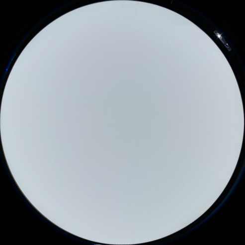
Before Black Level Compensation After Black Level Compensation 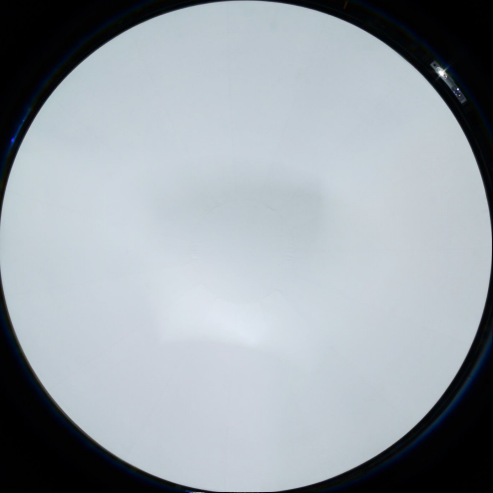
Before Brightness Balance After Brightness Balance