Quad Grid
The Quad Grid node is a patch that applies perspective to the individual planes of the user-defined mesh grid. This patch is developed to map projection onto surfaces of stair-like objects. In a typical setup, the Quad Grid node receives a source image as the input and outputs the modified image to the Display or Canvas node.

To apply perspective warping using the Quad Grid patch, do the following in the Patch Editor:
-
Create a mesh grid by entering X and Y values in the Grid Size parameter in the Settings panel.
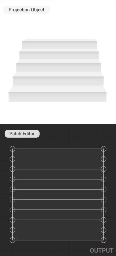
Typical settings for a projection onto a staircase-like object with horizontal planes (steps):
- The X value is 2 (the minimum number of key control points needed to define one column mesh grid). This value can be larger for projection mapping onto more complex objects.
- The Y value is equal to the total number of visible tread and riser surfaces.
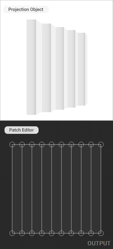
For a projection on a staircase-like object with vertical planes, the X and Y values are reversed.
 |  |
|---|---|
| Example of a patch grid for an object with horizontal planes. Grid Size: X=2, Y=10. | Example of a patch grid for an object with vertical planes. Grid Size: X=10, Y=2. |
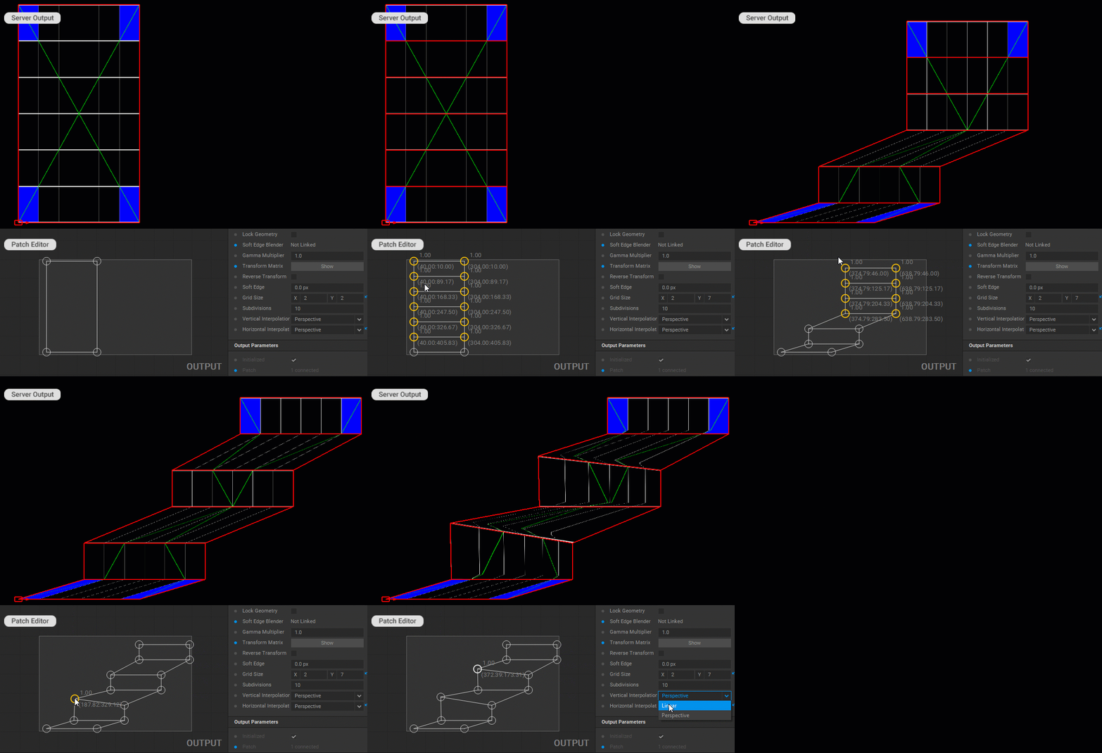
- In the Output panel, modify the warping mesh for the projected image by dragging the handles of the mesh control points for each grid plane.
- If the grid planes are transformed into trapezoidal shapes during the modification of the mesh grid, some warping artifacts may occur at the junction of the planes. To avoid this, select the Linear option for the Vertical Interpolation or Horizontal Interpolation parameters in the Settings panel to limit perspective distortion to horizontal or vertical grid planes.

In addition, working with the Quad Grid patch follows the general principles for working with patches outlined in the Editing Patches section of the documentation.


