Patch Editor Basics
Overview
Patch nodes (or Patches) such as Rectangle, Bezier Warp, Quad Warp, and others (see the full list of patch nodes) are designed to apply various types of image* geometry correction (warping), transformation, arrangement, and mapping. Extensive control for patch management is provided in the Patch Editor integrated into the Canvas (or Render Target) widget.** In addition, most operations with the patches can be performed directly from a computer keyboard connected to the **Server**.
* The term “image” refers to any static or dynamic media (i.e. video).** To access the Patch Editor, add the Canvas (or Render Target) widget to your workspace, then click the Patches tab on the top left of the widget to switch to the Patches view.
Patch Editor View
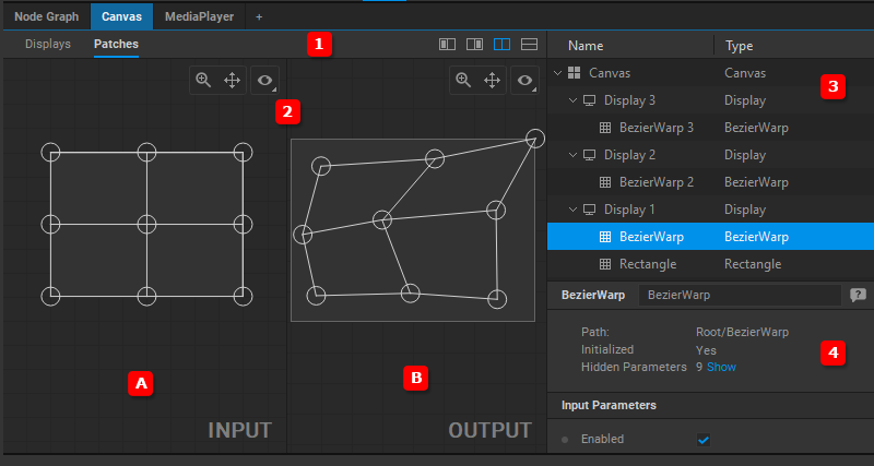
The Patch Editor view: (1) View mode bar, (2) Work area which is split into two parts: (A) Input panel and (B) Output panel, (3) Navigation tree, (4) Settings panel.
View Modes
There are four view modes of the work area available. You can toggle between them by clicking on the corresponding icon.
![]() Display only the Input panel.
Display only the Input panel.
![]() Display only the Output panel.
Display only the Output panel.
![]() Display both panels in the Vertical split view.
Display both panels in the Vertical split view.
![]() Display both panels in the Horizontal split view.
Display both panels in the Horizontal split view.
View Options
Additionally, the appearance of the Input and Output panels can be customized using the View Options panel, which can be opened by clicking the button in the top right corner of the panels.
The View Options panel allows the user to show or hide the following elements:
- Rulers Helps you accurately place and measure patches and displays.
- Labels Shows the names of the patches and displays.
- Coordinates Shows the coordinates of the positions of the patch control points.
- Live Image The interactively updated preview of the current video output.
- Reference Image The reference image is used as a background for more precise positioning of control points.
Zoom and Pan Functions
Тo zoom in and out of a specific area in the Input or Output panels of the Patch Editor, place the mouse cursor over the area, and use the mouse scroll wheel. Alternatively, click the button ![]() in the top right corner of the panel and move the mouse to change the magnification.
in the top right corner of the panel and move the mouse to change the magnification.
To pan a view, hold down the left mouse button while moving the mouse, or click the button ![]() in the top right corner of the panel and move the mouse.
in the top right corner of the panel and move the mouse.