Editing Patches
The settings of the patch node, just like any other node can be edited in the node graph. See Node Settings. However, the Patch Editor provides more advanced control over the adjustment of patch alignment, image geometry, or UV mapping.
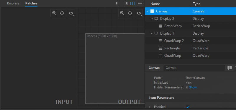
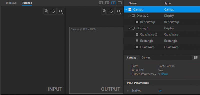
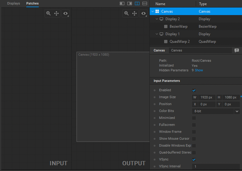
Selecting Patches for Editing
To select patches for editing, do one of the following:
In the Patch Editor:
- Click a patch in the navigation tree panel.
- To select multiple noncontiguous patches, Ctrl-click them in the navigation tree.
- To select multiple contiguous patches, click the first patch and then Shift-click the last patch in the navigation tree panel.
- To select all patches, click in the navigation tree panel and press
Ctrl+A.
In the Node Graph:
- Double-click on a patch node.
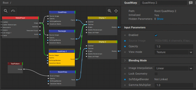
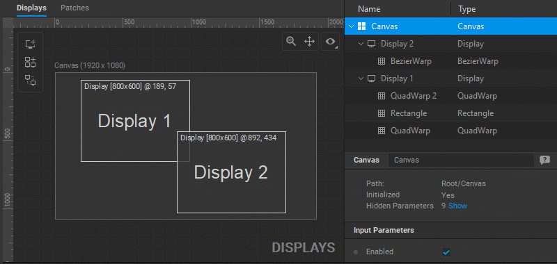
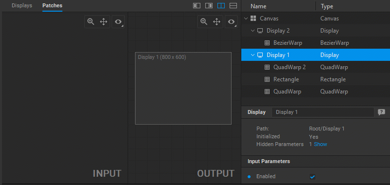
In the Display Editor:
- Double-click on a display to open all the patches connected to this display in the Patch Editor.
When multiple patches are selected, you can select patches of a particular type by clicking the number next to the patch type name in the Settings panel.
To switch to the editing of a contiguous patch, do one of the following:
- Press the
Zkey to select the next patch, or pressShift+Zto select the previous patch. - Right-click in the Input or Output panels and choose Select Next Patch or Select Previous Patch from the dropdown menu.
When a particular patch is selected, its Settings panel opens to provide control over its parameters.
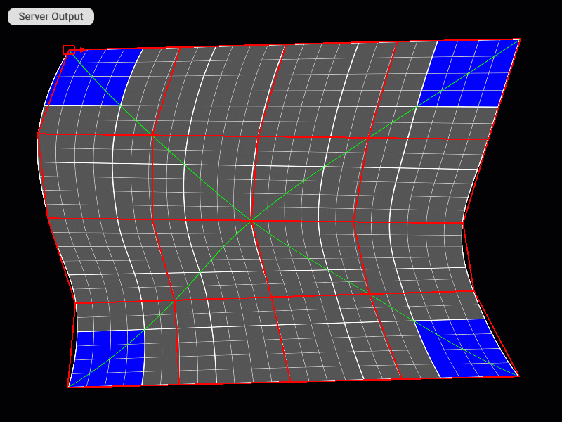
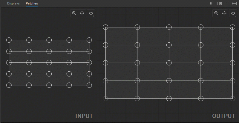
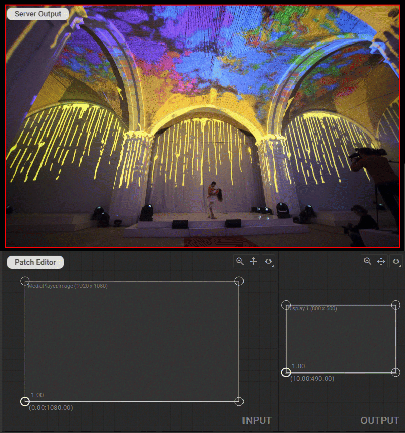
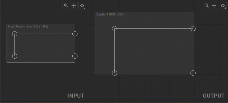
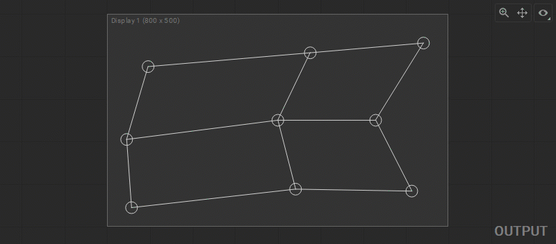
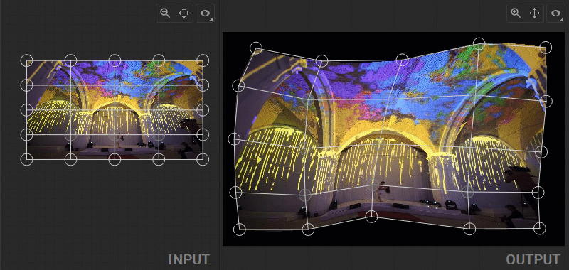
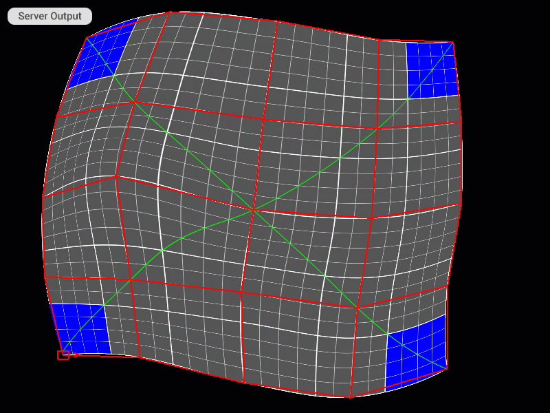
Modifying Output Image Geometry
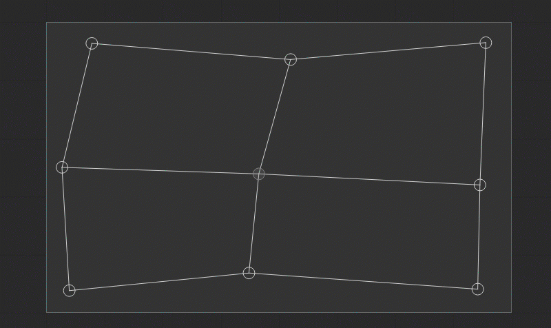
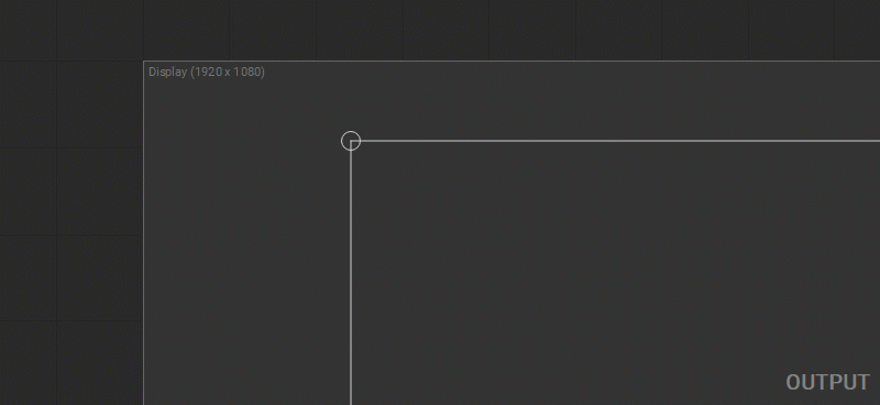
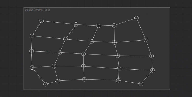
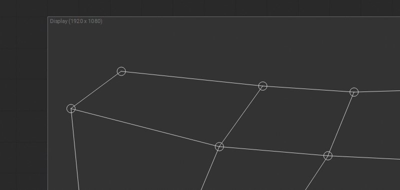
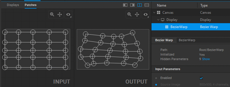
To change the output image geometry, select and drag the circular handles of the mesh control points (vertices) in the Output panel.
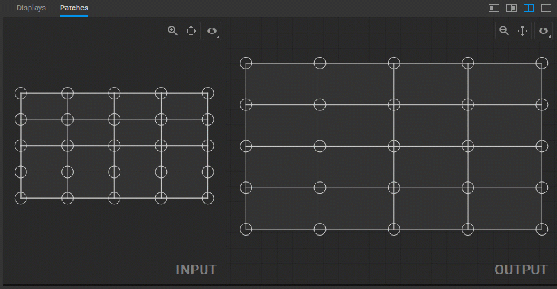
Multiple control points can be selected by Shift-clicking them one by one, or left-clicking and dragging a marquee box around them.
Note: It is recommended to have visual control over Screenberry output while making image geometry adjustments.
Adjusting UV Map
In Screenberry, a source image received by a patch node is UV mapped onto a geometry defined by a patch. To adjust the UV mapping of the input image, select and drag the circular handles of the mesh control points (UV map vertices) in the Input panel.
Control Points Coordinates
To show control points coordinates, do one of the following:
- Press the
Spacebar. - Right-click in the Input or Output panels and select Show Coordinates from the dropdown menu.
- Select Show Coordinates in the View Options panel.
To change control point coordinates manually, select the control point and press the Enter key, or right-click on the control point and select Set Position from the dropdown menu. Enter X and Y coordinates in the dialog window.
Note: The coordinate origin (0,0) is located at the top-left corner.
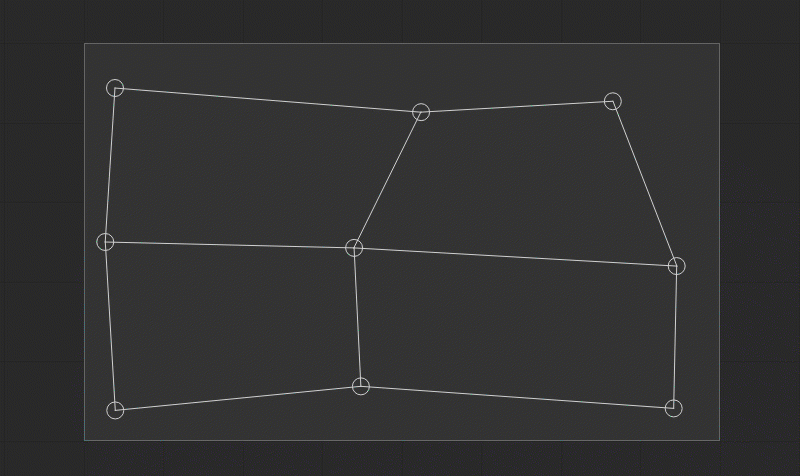
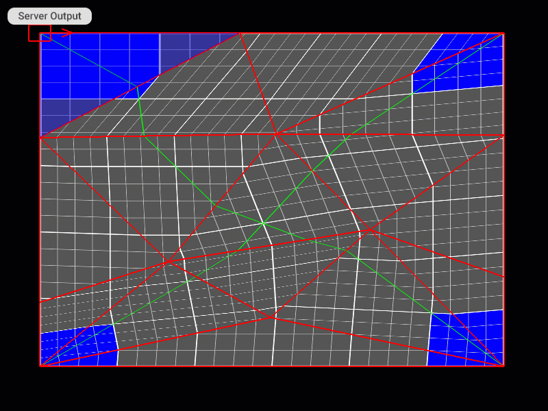
Flipping and Rotating Patch Indexes
You can apply a vertical flip or 90 degrees clockwise rotation to the source media in the Geometry Layout Area or to a UV selection in the UV Layout Area. All vertices of the geometry mesh in the Output panel or a UV map in the Input panel can be flipped vertically or rotated 90 degrees clockwise at once. To flip, select any of the patch control points and press the F key, or right-click on a control point and select Transform>Flip from the dropdown menu. To rotate, select any of the patch control points and press the R key, or right-click on a control point and select Transform>Rotate Indexes from the dropdown menu.
Note: Selecting a control point when flipping or rotating the mesh helps to understand which transformation of geometry or UV layouts has been applied.
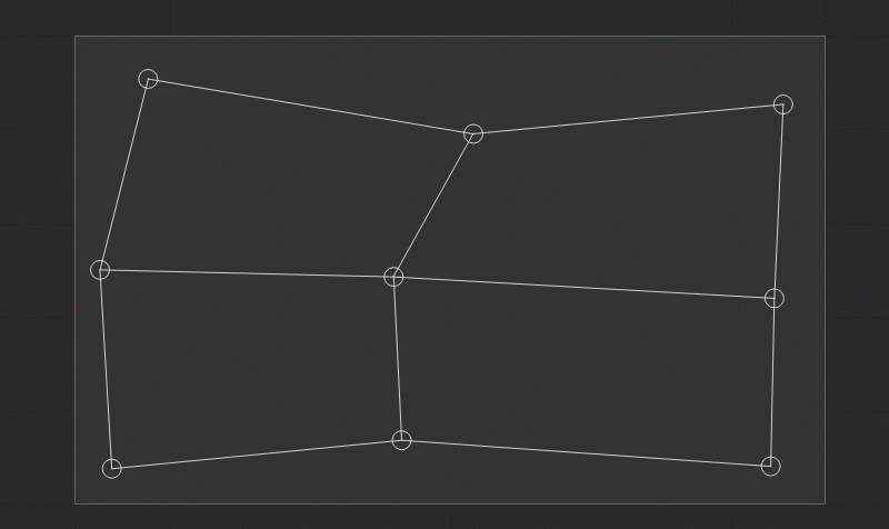
Modifying the Density of a Mesh Grid
You can change the density of the mesh grid to achieve more control over the image geometry correction. To change the mesh grid density, use the related keyboard shortcut, or right-click in the Patch Editor work area and select Subdivide/Merge/[Function] from the dropdown menu. The following functions and keyboard shortcuts are available:
- Increase Subdivision (
Ctrl+X) splits the polygons by cutting them in half and adding new vertices. - Decrease Subdivision (
Ctrl+Shift+X) combines the adjacent polygons by removing their shared boundary. - Subdivide Columns (
Ctrl+Shift+Right) splits the polygons of all columns by cutting them in half, and adding new vertices. - Merge Columns (
Ctrl+Shift+Left) combines the adjacent polygons of all columns by removing their shared boundary. - Subdivide Rows (
Ctrl+Shift+Up) splits the polygons of all rows by cutting them in half, and adding new vertices. - Merge Rows (
Ctrl+Shift+Down) combines the adjacent polygons of all rows by removing their shared boundary.
Using Smart Guides and Guidelines
When the position of the control points is edited, the gray-dotted horizontal and vertical smart guides are displayed. They provide a visual reference to the previous coordinates of the control point and help with its alignment along the prior axes.
Besides, when editing the Rectangle patch the additional diagonal gray dotted smart guide is displayed to indicate the aspect ratio of the source image.
To add custom guidelines, right-click in the panel and select Guideline Editor from the dropdown menu. In the opened dialog box, do one of the following:
- Create the guideline grid by entering the number of Columns and Rows and pressing the Add Grid button.
- Add individual guidelines by entering their coordinates and pressing the Add Horizontal Guideline or Add Vertical Guideline buttons.
Press the Clear All button if you want to remove all guidelines. After the guidelines setup is finished, press the OK button to add guidelines to the panel.
Snapping
By default, the automatic snapping option is enabled. When you change the position of a control point, it snaps to the guidelines, smart guides, output canvas edges, and other control points if placed near them. To disable snapping temporarily while dragging a control point, hold down the Shift key.
Vertical and Horizontal Alignment of the Control Points
To align the selected control points horizontally press Shift + H or right-click on the selected control points and choose Align Horizontally from the dropdown menu. To align the selected control points vertically press Shift + V or right-click on the selected control points and choose Align Vertically from the dropdown menu.
You can also constrain the movement of the control points while editing:
- To the horizontal axis by pressing the
Hkey or right-clicking on the control point and selecting Constrain Horizontally from the dropdown menu. - To the vertical axis by pressing the
Vkey or right-clicking on the control point and selecting Constrain Vertically from the dropdown menu.
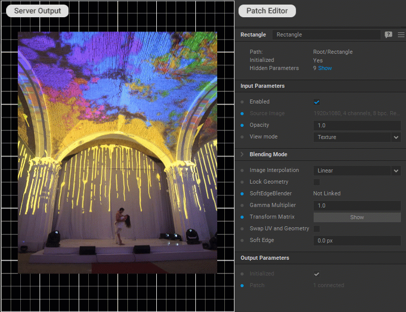
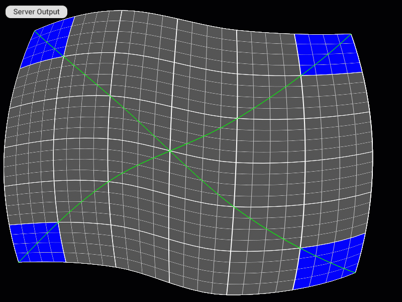
Previewing Patch Output
To have visual control over patch transformations, you can display the patch output image. This image is automatically updated every time a patch is modified. In the Output panel, this Live Image is a snapshot of the current video output from the media server, while in the Input panel, it shows the source image feed received by the patch. To show/hide the Live Image, do one of the following:
- Press
Shift+F5(the panel should be in focus). - Select/deselect the Live Image > Show option from the View Options panel.
- Right-click in the panel and select/deselect the Show Live Image checkbox in the dropdown menu.
If you need to update the Live Image manually, do one of the following:
- Press
F5. - Press the Live Image > Image [ Refresh ] button in the View Options panel.
- Right-click in the panel and select the Get Live Image from Server option from the dropdown menu.
Using a Reference Image
A reference image (for example, the photo of the object the warping is applied to) can be used as a background to help position control points with more precision. To load a reference image, do one of the following:
- Press the Reference Image > Image [ Load ] button in the View Options panel.
- Right-click in the panel and select the Load Reference Image option from the dropdown menu.
To show/hide the reference image, do one of the following:
- Select/deselect the Reference Image > Show option from the View Options panel.
- Right-click in the panel and select/deselect the Show Reference Image checkbox in the dropdown menu.
These actions will open the image loading dialog box if no reference image has previously been loaded.
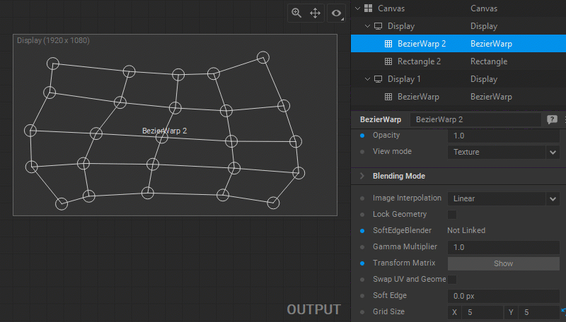
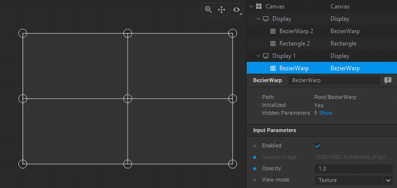
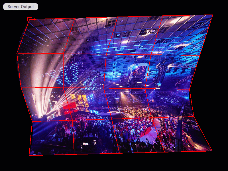
Selecting Display Modes for the Output
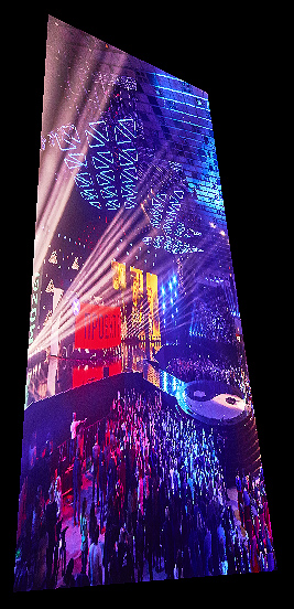
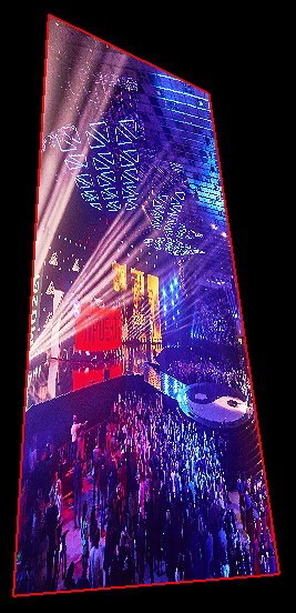
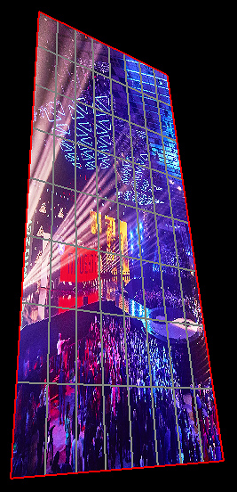
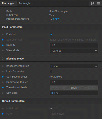
You can select one of the three available display modes by choosing the View Mode parameter in the Settings panel of the patch:
- Textured shows the output image only.
- Textured + Cage shows the output image and mesh grid (red lines).
- Textured + Wireframe shows the output image, mesh grid (red lines), and subdivision wireframe (grey lines).
 |  |  |
|---|---|---|
| Example of the PerspQuad patch output in Texture mode | Example of the PerspQuad patch output in Texture + Cage mode | Example of the PerspQuad patch output in Texture + Wireframe mode |
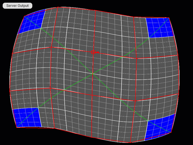
Modifying Density of a Subdivision Wireframe
The overall smoothness of the output image (the result of warping applied by the patch) can be improved by increasing the density of a subdivision wireframe. This results in a finer warping grid.
You can change the number of subdivisions by entering a value for the Subdivisions parameter in the Settings panel of the patch. The maximum value is 256, the minimum is 1, and the default is 5.
An example of how changing the wireframe subdivisions from 5 to 20 improves the smoothness of the output image
Note: The number of subdivisions determines the wireframe density. A higher density increases warping precision but requires more processing time, a lower one does the opposite.
Selecting the Interpolation Algorithm
To change the interpolation algorithm for translating pixel values of the patch, select the Linear or Nearest-neighbor option for the Image Interpolation parameter in the Settings panel.
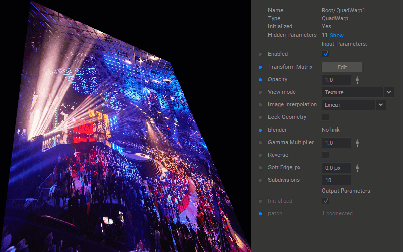
Changing Patch Opacity
To adjust the patch opacity, change a value for the Opacity parameter in the Settings panel.
Softening Patch Edges
To fade the edges of a patch into transparency (feather), enter the soft edge width in pixels for the Soft Edge parameter in the Settings panel of the patch.
Applying Transformations to Patches
Various transformations can be applied to the patch by using the transformation matrix. Click the Edit button for the Transform Matrix parameter in the Settings panel of the patch to edit the matrix values.
![]()
Examples of transformations:
| sx | 0 | 0 | 0 |
|---|---|---|---|
| 0 | sy | 0 | 0 |
| 0 | 0 | 1 | 0 |
| 0 | 0 | 0 | 1 |
Scale: sx specifies the scale factor along the x-axis. sy specifies the scale factor along the y-axis.
| 1 | 0 | 0 | 0 |
|---|---|---|---|
| 0 | 1 | 0 | 0 |
| 0 | 0 | 1 | 0 |
| tx | ty | 0 | 1 |
Translation: tx specifies the displacement along the x-axis. ty specifies the displacement along the y-axis.
| 1 | shy | 0 | 0 |
|---|---|---|---|
| shx | 1 | 0 | 0 |
| 0 | 0 | 1 | 0 |
| 0 | 0 | 0 | 1 |
Shear: shx specifies the shear factor along the x-axis. shy specifies the shear factor along the y-axis.
| 1 | 0 | 0 | tx |
|---|---|---|---|
| 0 | 1 | 0 | ty |
| 0 | 0 | 1 | 0 |
| 0 | 0 | 0 | 1 |
Tilt: tx specifies the tilt factor along the x-axis. ty specifies the tilt factor along the y-axis.
![]()
Locking Patch Geometry
To avoid further (accidental) editing of the patch geometry, select the Lock Geometry checkbox in the Settings panel of the patch.
Note: Patches with the Lock Geometry checkbox selected are skipped during cycling through the patches using
Z(next patch) andShift+Z(previous patch) keyboard shortcuts directly on the Server.
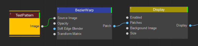
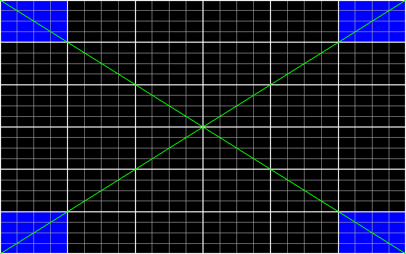
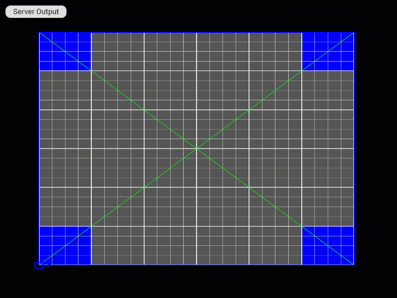
Using Test Pattern
For more efficient and convenient patch editing, consider using a grid test pattern generated by the Test Pattern node. Connect this node to the patch node as the source image, and adjust the test pattern's appearance by modifying the parameters in the node settings.
Restoring Patch Default Settings
To restore the default settings of a patch, right-click on the patch name in the navigation tree and select Reset Patch from the dropdown menu.
Using Keyboard Shortcuts to Edit Patches
Keyboard shortcuts can be used for more effective patch editing. If necessary, manual calibration can also be performed directly on the server, without using the Screenberry Panel, and requires only a keyboard connected to the Server computer. Keyboard shortcuts list:
| Action | Panel Shortcut | Server Shortcut |
|---|---|---|
| General | ||
| Enter/Exit calibration mode | Ctrl + C | |
| Show keyboard shortcuts list | F1 | H or F1 |
| Undo | Ctrl + Z | Ctrl + Z |
| Redo | Ctrl + Shift + Z | Ctrl +Shift + Z or Ctrl + Y |
| Reset patch geometry and UV | Ctrl + R | Ctrl + R |
| Patch Selection | ||
| Select the next patch | Z | Z |
| Select the previous patch | Shift + Z | Shift + Z |
| Patch Editing Modes | ||
| Switch to Geometry mode (the mesh is highlighted in red) | G (press G again to show/hide subdivisions) | |
| Switch to UV mode (the mesh is highlighted in green) | U | U |
| Switch to Geometry+UV mode (the mesh is highlighted in blue) | Y | |
| Show/hide all patch cages and wireframes | Space | |
| Increment Value (for movement, scale and rotation operations) | ||
| Increase increment | + or = | = |
| Decrease increment | – (minus) or _ (underscore) | _ (underscore) |
| Reset increment to default | 0 (zero) | 0 (zero) |
| Control Points | ||
| Select control point | Arrow keys | Arrow keys |
| Select mesh faces (for the TriMesh patch only) | Ctrl + Arrow keys | |
| Move control point | W, S, A, D | W, S, A, D |
| Move control point in smaller (1/10) increments | Shift + W, S, A, D | Shift + W, S, A, D |
| Control Cage | ||
| Move cage | Ctrl + W, S, A, D | Ctrl + W, S, A, D |
| Move cage in smaller (1/10) increments | Ctrl + Shift + W, S, A, D | Ctrl + Shift + W, S, A, D |
| Scale cage | Alt + W, S, A, D | Alt + W, S, A, D |
| Scale cage in smaller (1/10) increments | Alt + Shift + W, S, A, D | Alt + Shift + W, S, A, D |
| Rotate cage clockwise | E | E |
| Rotate cage clockwise in smaller (1/10) increments | Shift + E | Shift + E |
| Rotate cage counterclockwise | Q | Q |
| Rotate cage counterclockwise in smaller (1/10) increments | Shift + Q | Shift + Q |
| Flip cage vertically | F | F |
| Rotate cage 90 degrees clockwise | R | R |
| Control Point Handles | ||
| Rotate handle 90 degrees clockwise | Ctrl + E | |
| Rotate handle clockwise in smaller (1/10) increments | Ctrl + Shift + E | |
| Rotate handle 90 degrees counterclockwise | Ctrl + Q | |
| Rotate handle counterclockwise in smaller (1/10) increments | Ctrl + Shift + Q | |
| Control Cage Density | ||
| Increase cage subdivision | Ctrl + X | Ctrl + X |
| Decrease cage subdivision | Ctrl + Shift + X | Ctrl + Shift + X |
| Increase rows subdivision | Ctrl + Shift + Up Arrow | Ctrl + Shift + Up Arrow |
| Decrease rows subdivision | Ctrl + Shift + Down Arrow | Ctrl + Shift + Down Arrow |
| Increase columns subdivision | Ctrl + Shift + Right Arrow | Ctrl + Shift + Right Arrow |
| Decrease columns subdivision | Ctrl + Shift + Left Arrow | Ctrl + Shift + Left Arrow |
| Increase wireframe subdivision | Ctrl + = | Ctrl + = |
| Decrease wireframe subdivision | Ctrl + _ (underscore) | Ctrl + _ (underscore) |
| Blending | ||
| Rebuild blend maps (if the SoftEdgeBlender node is connected) | Ctrl + B | Ctrl + B |
| Increase transparency falloff area at the selected control point (5% increments) | [ | [ |
| Decrease transparency falloff area at the selected control point (5% increments) | ] | ] |
Visual Examples of Using Keyboard Shortcuts on the Server
Selecting the Patch
Patch Editing Mode Selection
Selecting and Moving Control Points
Selecting Faces of the Patch Mesh (only for the TriangleMesh patch)
Moving and Scaling All Control Points of the Patch Mesh at Once
Changing the Editing Step Increment
Flipping and Rotating the Patch Mesh
Changing the Direction of the Control Point Handle
Modifying the density of the patch grid